SpinFire Web uses .scs files but can view the older .hwf format from previous versions. Deployment scripts automatically update your previous pipelines using the CAD to SpinFire Web action to use the new .scs format.
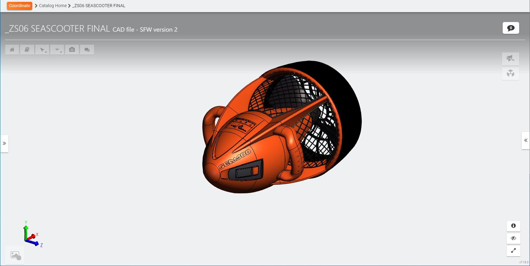
SpinFire Web allows you to view and comment on a 3D model. You can take a snapshot of the image at any time, save it to a file, and add it to the catalog.
Rotate
Left-click+Drag
Zoom in
Middle-click+Drag towards you
Rotate mouse the wheel away from you
Zoom out
Middle-click+Drag away from you
Rotate the mouse wheel toward you
Pan
SHIFT+Left-click+Drag
The Assembly and Views browsers give you the option to search for and sort items.
Search
Find an item in the browser tree. Search always performs a partial search.
Sort
Sort in alphabetical order when selected.
Assembly tree parts
Hide, show, and select parts in the assembly tree.
PMI
Hide and show any PMI data that's associated to the model.
Measurements
Hide, show, and select measurements made in SpinFire Web.
Notes
Hide, show, and select Notes made in SpinFire Web.
Standard Views
Switch between Isometric, Front, Back, Top, Bottom, Right, and Left standard views.
User Views
When using the Draw Text tool, a markup is created in its own user view. The User Views selections enable you to view those markups.
The user view also contains the part camera view.
CAD Views
If the model contains a CAD view, it can be selected here.
Expand this tab by clicking on the orange tab to view attributes about all its related files. Select and filter attributes to one's liking.
Turn a level of transparency on for the selected part.
Bounding Box
Select to show the axis-aligned bounding box.
Home
Click the Home button to reset the camera view back to the star.
PMI data
If the model contains PMI/GD&T data, toggle the information in the graphical view on and off.
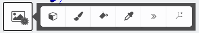
Select Element
Smart Edge
Surface Angle
Face Distance
Point to Point Distance
Set to use the mouse to select parts of the model.
Smart Edge Dimension Tool.
Hover cursor over an edge
Select edge
Move cursor to position dimension
Surface Angle Dimension Tool.
Select 1st planar surface
Select 2nd planar surface
Move cursor to position dimension
Face Distance Dimension Tool.
Select 1st planar surface
Select 2nd planar surface
Move cursor Up/Down to position dimension
Then move cursor Left/Right to position dimension
Point to Point Distance Tool.
Select any surface for 1st point
Select any surface for 2nd point
Move cursor to position dimension
Draw a Circle
Draw a circle to highlight a given area.
Click once to start the circle.
Move the mouse to increase or decrease the diameter.
Click again to finish.
Freehand Drawing
Use the Freehand Drawing tool to draw a line.
Click to start.
Move the mouse to draw a continuous line.
Click again to finish.
Draw Rectangle
Draw a rectangle to highlight a given area.
Right-click and drag the mouse to start the rectangle.
Move the mouse to give it smaller or larger dimension.
Click once again to finish.
Draw Text
Place text anywhere in the model and create an associated User View.
Click to start.
Click in the draw text windows to enter text.
Enter text.
Click elsewhere to stop text entry.
Move to the desired location.
Use the Select Element tool to finish.
Click on the associated User View to view the drawn text.
Orbit Part
Orbit Point
Turntable Camera
Walk
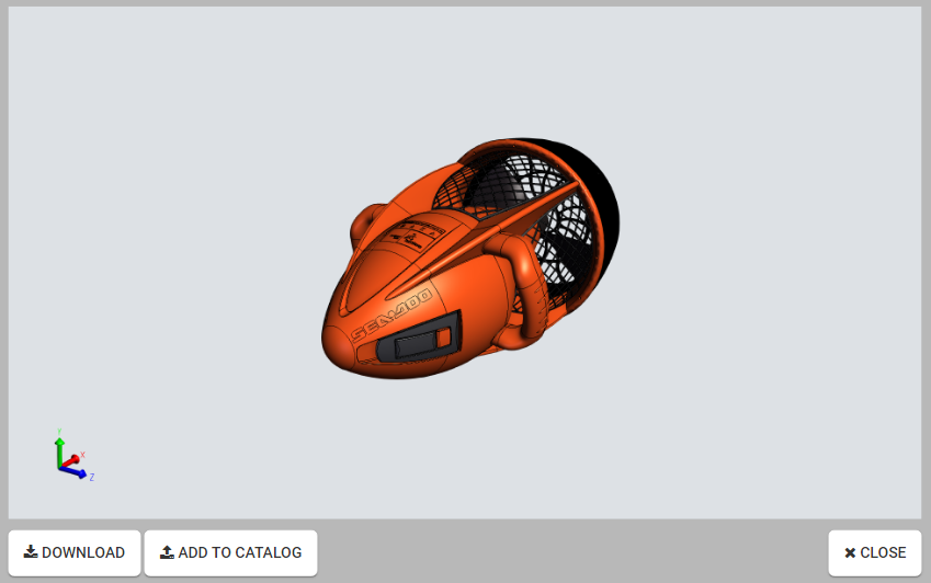
Take a snapshot image of how the model appears on screen.
Rotate, zoom, pan, change background color, and set your measurements and markups before taking your snapshot.
Click the Download button to download the image as a .png file to your local drive. The default file name is capture.png.
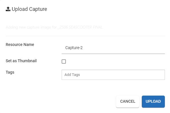
Click the Add to Catalog button to add the image file as a new resource associated with the part.Enter a name for the new resource.Select the Set as Thumbnail checkbox to.
Click Close to exit.
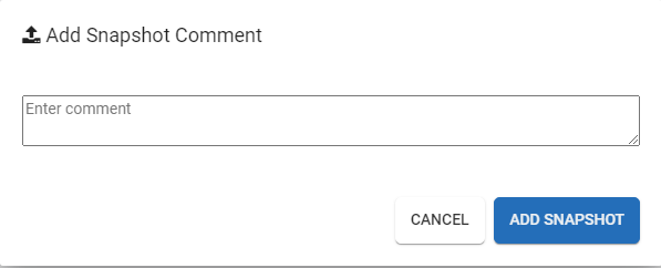
Shared State Snapshot
Take a snapshot image of the current state of the model in SpinFire Web, add it with a comment to the Comments section to collaborate with others in your organization.
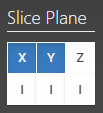
Sectioning
Select the X, Y, and/or Z axis to slice. One, two or all three planes can be used at once to section the model.
Left-mouse-drag a section plane to move it across the model.
Toggle the I button to flip the sectioning plane.
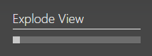
Exploded Assembly
Use the slider bar to increase the distance between parts and away from the center.
Perspective or orthographic projection
Click to toggle the project mode between perspective and orthographic.
Flat/Shaded (render mode)
Click to toggle the render mode between flat and shaded.
Change background color
Change the background color with a color selector.
Change Part Color
Click to select a color from the color picker to change the color of the selected part.
Momentum
Enable the momentum to auto-spin the model.
Once enabled, hold the left mouse button down, move in a direction and release. The model will continue to spin.
The model spins at a rate based on the speed the mouse was moving when the button was released.
Axis Triad
Toggles the axis triad off and on.
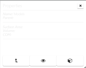
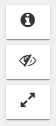
Properties Toggle - Hide/show the properties when clicking on a part.
UI Toggle - Hide/show UI elements (browser, toolbars and tools)
Fullscreen Toggle - Click to view the model in the browser's full screen mode. (In most browsers, This can also be achieved with the F11 key.)
Use the breadcrumb path to navigate through pages you have visited.
Click Part View to return to the part view.
JavaScript errors detected
Please note, these errors can depend on your browser setup.
If this problem persists, please contact our support.